 Add Material Callout
Tool summary :
- Automatically calls out items on auto detailed drawings. The drawings need to be current with the 3D model.
- Add Material Callout can automatically add a submaterial mark label or hole symbol or bolt label in combination with optional leader lines and pointers.
- To call out auto detailed material, the drawing needs to be a member detail (including a group member detail) or submaterial detail or erection view drawing .
- Holes and bolts -- user added or auto detailed -- can be called out on those same drawing types plus on drawing types such as sheets and sheet outlines.
- If the drawing is out of date, you may get an needs-to-be-detailed warning .
- See (on this page):
Also see :
| VIDEO
|

|
Objects > Material Callout > Add is used to place material callouts, bolt callouts and hole symbols.
|
|
| VIDEO
|

|
Objects > Material Callout > Add is used to call out rebar from a floor slab. Because the rebar was modeled and then auto detailed, a Edit Rebar Item window is opened and its fields are automatically populated. The Rebar Item object " Thumbnail " and " Thumbnail scale " options are demonstrated.
|
|
page 1 | contents | objects > material callout > add
 Examples :
Pcmk only

|
Mtrl type & pcmk

|
Mtrl type, size & pcmk

|
|
|
|
|
The " Material designation type " on the Edit Label window lets you set whether the label shows the ' Piecemark only '; or the " Material type & pcmk " or the " Mtrl type, size & pcmk ." To add a material callout, select an auto-detailed material ( polygon ) in step 2 .
|
Bolt type only

|
Bolt size and type

|
|
|
|
|
The " Bolt designation type " on the Edit Label window lets you set whether the label shows the ' Bolt type only ' or the " Bolt size and type ." To add a bolt callout, select an auto-detailed bolt in step 2 .
|
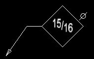
Hole symbol
|
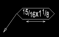
Slot symbol
|
|
|
|
|
A hole symbol or slot symbol is created automatically when you click an auto-detailed hole in step 2 .
|
|
|
This slot symbol with a segmented leader line was created by selecting a slot in step 2 , then using left-click ( Pointer ) twice, middle-click ( Hole Sym ) once.
|
page 1 | contents | objects > material callout > add | top
 Needs-to-be-detailed warning :
Since Add Material Callout gets its information about material from the 3D model in Modeling , the member detail , submaterial detail , or erection view drawing may give you a warning message similar to the following if that drawing is not up to date. You can also get a message like the following for auto detailed bolts and holes.

|
This drawing needs to be detailed before this item can be reviewed.
|

|
|
|

|
|
|
For erection views and bolts only: If your current drawing is an erection view that is out of date, you may not always get current information about a bolt (e.g., the bolt's length might be wrong). For member details, a needs-to-be-detailed message like that shown above will prevent this from happening. Also, since there are no bolts on submaterial details, this does not happen for submaterial details. The fix for this problem is to always keep your 2D erection views up to date. Of course, user-added bolts and holes will never produce a message like the above.
page 1 | contents | objects > material callout > add | top
 Step-by-step instructions :
The following instructions assume that you are using a 3-button mouse, that the User and Site Options > General > " Point location target " is set to ' Fancy ' (  ), and that you use mouse bindings similar to those shown in these illustrations. Right-click ( Return ) when you are done.
Before using this tool:

|
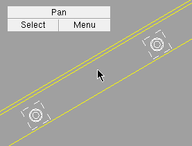
1 . Invoke Add Material Callout .
|
|
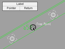
2 . Select an auto-detailed material ( polygon ) or any bolt or any hole . A needs-to-be-detailed warning may appear.
|
|
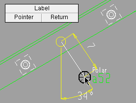
3 . Left-click ( Pointer ) places the head of the pointer where the target (  ) is at. Note that a temporary callout label is shown. If the item selected in step 2 were a hole or slot, a temporary hole or slot symbol would be shown. ) is at. Note that a temporary callout label is shown. If the item selected in step 2 were a hole or slot, a temporary hole or slot symbol would be shown.
|
|
4 . Middle-click ( Label ) places the end of the pointer where the target (  ) is at. For a hole or slot, the binding reporter says Hole Sym instead of Label . ) is at. For a hole or slot, the binding reporter says Hole Sym instead of Label .
Alternatives: You can left-click ( Pointer ) before middle-click ( Label ) to create a segmented leader line as described in note 2 . Right-click ( Return ) is an alternative described in note 3 .
|
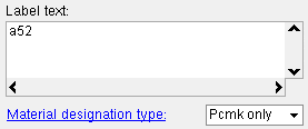 |
5 . On the Edit Label window ( Hole Symbol Input window for a hole), enter the settings that you want applied to the callout, then press " OK ."
|
|
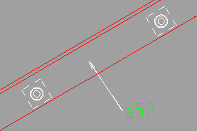
5 . The material, bolt or hole callout has been added. The Material Callout operation is done.
|
Note 1: To invoke Add Material Callout , choose Objects > Material Callout > Add , or use a keyboard shortcut (if one has been set up), or click the icon pictured above (if it has been placed on your tool bar).
Note 2: An arrowhead is placed at the point location target (  ) the first time that you left-click ( Pointer ). Each additional left-click adds a new line segment to the leader line.
|
|
This material callout with a segmented leader line was created by selecting an angle in step 2, then using left-click ( Pointer ) twice, middle-click ( Label ) once.
|
Note 3: In step 4, doing a right-click ( Return ) instead of a middle-click ( Label ) would end the Add Material Callout operation but retain any leader lines that you already laid out, thus giving you leader lines without a label .
<  |
|
|
|
This leader line with no label or hole symbol was created using left-click ( Pointer ) four times, right-click ( Return ) once.
|
Note 4: You can add multiple leader lines with multiple heads.

|
Hold down the Shift key to get a New Head mouse binding.
|
Tip 1: When you are done, you can Undo to remove the callout you have added.
Tip 2: As shown here , you can drag a label (or hole symbol) and stretch the pointer that is attached to it. To detach the pointer from the label (or hole symbol), hold down the Shift key while dragging the label (or hole symbol). Alternatively, you can detach the pointer by dragging it away from the label (or hole symbol).
page 1 | contents | objects > material callout > add | top
 Add Material Callout ( Drawing Editor )

 Examples :
 Needs-to-be-detailed warning :
 Step-by-step instructions :
![]() ), and that you use mouse bindings similar to those shown in these illustrations. Right-click ( Return ) when you are done.
), and that you use mouse bindings similar to those shown in these illustrations. Right-click ( Return ) when you are done.


) is at. Note that a temporary callout label is shown. If the item selected in step 2 were a hole or slot, a temporary hole or slot symbol would be shown.

) is at. For a hole or slot, the binding reporter says Hole Sym instead of Label .


) the first time that you left-click ( Pointer ). Each additional left-click adds a new line segment to the leader line.


